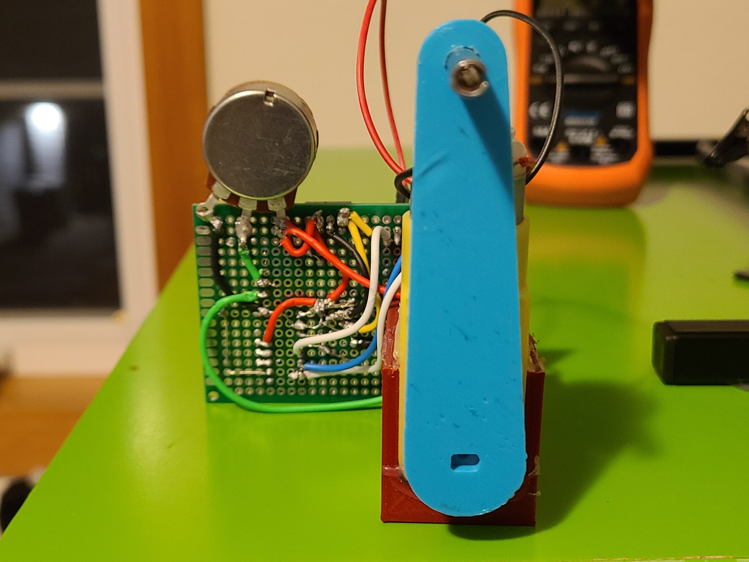
This was a 2 week project in which I challenged my self to implement some concepts I had been learning in my control theory classes about PID loops. I thought I would try and control a motor. I had access to a brushed DC motor and a potentiometer, some other components and a 3D printer.
The code for this was all written in embedded C toggling on and off 2 GPIO pins dependent upon the difference of the set point from the potentiometer to the position of the motor. The theory was very simple to implement, the hard part was learning how to 3d model and how to put the whole system together.
The long and short of it is that I connected a potentiometer to the output of a dual shaft DC brushed motor with the help of some glue, heat shrink, and an enclosure I modeled in Fusion 360. On the other end of the shaft I through on a lever arm with another shaft on it.
On the other end of the potentiometer I drew up a circuit that would use use a microcontroller, motor controller, buck converter, and some other discreet parts. Microcontroller to implement the logic, motor controller to drive the motor, buck converter so the microcontroller could use the same power supply that drove the motor.
The microcontroller I used was a Atmel atmega328p the same one that comes on an Arduino Uno. Instead of using the Arduino IDE I went ahead and installed the Atmel Arm GNU toolchain to write some code that wasn’t dependent of the Arduino environment.
There is a second potentiometer that I am using as a sensor for the system. For a system to be control there must be a sensor letting the controller know what state the system is in. In this system there are 2 potentiometers one as the the control the other as the sensor. The purpose of this system is that whatever position the control potentiometer is in the motor will turn to put the sensor in the same position.
